**Setup Converter**
The setup converter is a command line tool that can convert transient image files from one virtual setup into another.
# Overview
The Setup converter can apply changes to the scene setup that do not require a rerendering of the scene. As the bundled scene are stored as unwarped transient histograms, they essentially contain the light that arrive at the reflector. The setup converter allows to change the position and resolution of the virtual camera that observes the scene.
!!! WARNING
The setup converter always performs a resampling of the input file. This is a lossy operation and thus should be done ideally only once. (Similar to working with JPEG files).
The main purpose of the tool is to make the measurements more realistic. Usually geometric constraints prohibit sensing the whole reflector and time of flight cameras often have a lower resolution than the renderings. With the setup converter, images can be converted into a setup where only a part of the wall with a possibly lower resolution is observed.
Due to the huge variety of possible setups, the benchmark only compares results from the original input data. Nonetheless, contestants are encouraged to evaluate their algorithm also with these more realistic data sets.
# Download & Installation
The Setup convert is distributed as C++ source files and part of the [Toolbox](/toolbox). All dependencies are bundled, so compilation should be pain-free.
# Usage
The order of the parameters is arbitrary. Each parameter is passed as the parameter name (always starting with a `-`) and its value, separated by a blank. Example invocation:
~~~~~~~
SetupConvert.exe -i "Input.ti"
-res 360 128 128 -t 0 4
-q0 -0.12 0.18 -q1 0.15 0.2 -q2 -0.12 0.03 -q3 0.15 -0.03
-sf 5 -tf 2
-o "Output.ti"
~~~~~~~
The parameters are:
Parameter | Explanation
-----------|------------
`-i` | Input file
`-o` | Output file
`-res t u v` | t, u and v resolution of the new image
`-t min max` | temporal range of the new image
`-q0`, `-q1`, `-q2`, `-q3`| new corner points
`-sf` | filter kernel size for spatial filtering in pixels of the input image
`-tf` | filter kernel size for temporal filtering in pixels of the input image
The 4 corner points $q_0$..$q_3$ define which part of the reflector is seen by the camera:
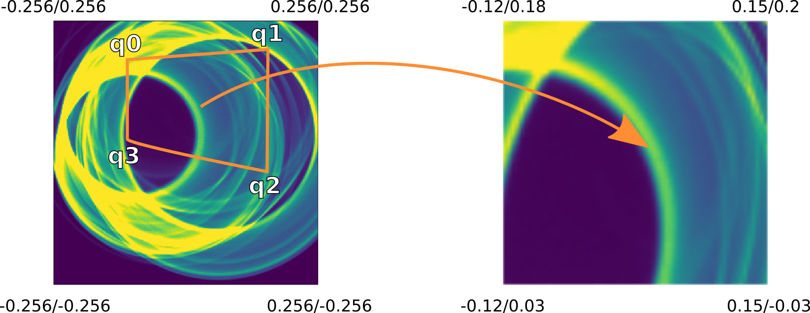
Mathematically, the correspondences of the four old and four new corner points is used to compute a homography.
If the spatial and temporal filter size are omitted, they are automatically chosen based on the input and output resolution. Depending on the new corner point, this might not be appropriate in every situation.